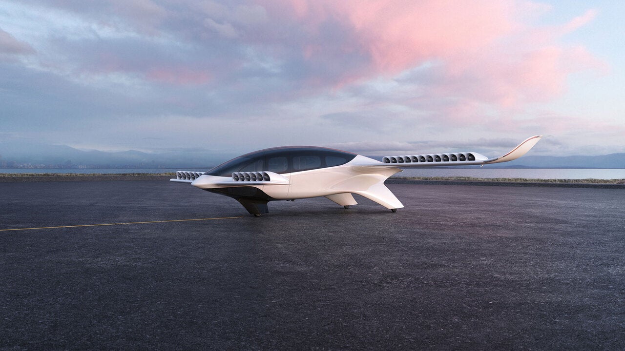
Lilium Seven-Seater eVTOL Jet, Germany
German aerospace company Lilium unveiled its electric vertical take-off and landing (eVTOL) Lilium Jet in March 2021.
German aerospace company Lilium unveiled its electric vertical take-off and landing (eVTOL) Lilium Jet in March 2021.
German aerospace company Lilium unveiled its electric vertical take-off and landing (eVTOL) Lilium Jet in...
Read More...
In June 2021 US-based aircraft manufacturer Archer Aviation unveiled its inaugural electric vertical take-off and...
Read More...
Bye Aerospace launched the eFlyer 800 in April 2021. An eight-seat, all-electric aircraft, it was...
Read More...
HondaJet Elite S is a new light business jet introduced by US-based aircraft manufacturer Honda...
Read More...
French aircraft manufacturer Dassault Aviation introduced the Falcon 10X, a new advanced high-speed, ultra-long-range business...
Read More...
Slovenian aerospace company Pipistrel is developing the Heavy Cargo Hybrid vertical take-off and landing (VTOL)...
Read More...
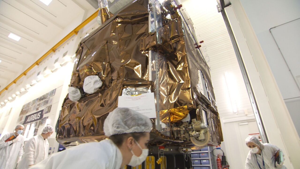
Pléiades Neo 3 is the first earth observation satellite of the Pléiades Neo constellation being...
Read More...
Superbird-9 is a yet-to-be-launched, fully digital telecommunications satellite being developed for SKY Perfect JSAT, a...
Read More...
The Valkyrie aircraft, formerly Cobalt 50 Valkyrie, was launched by its previous developer Cobalt Aircraft...
Read More...
The Wideband Global SATCOM (WGS) system is a high-capacity communication satellite, previously known as the...
Read More...